GEOD
image (3)
Automatic extraction of a topographic profile
It is possible with GEOD to extract a topographic profile from a DEM and save it into a GEOD script, thus providing the starting point for drawing a cross-section.
Summary
- Automatic computation of a topographic profile
- Specifying the DEM scale with reference
- Obtaining the topographic profile between two points with profile
- Obtaining the topographic profile along any curve with profile
- Scanning a DEM with xprofile
- Scanning a DEM with yprofile
- Drawing contour lines on the DEM with contour
Automatic computation of a topographic profile
GEOD can extract a topographic profile from a DEM and save it in a GEOD script, thereby providing the starting point for drawing a cross-section.
Specifying the DEM scale with reference
Before doing so, it is necessary to define the scale of the DEM with the reference subcommand:
reference xmin ymin xmax ymax
where:
- xmin and ymin give the field coordinates of the lower-left corner of the DEM. In general, one will take xmin = 0 and ymin = 0.
- xmax and ymax give the field coordinates of the upper-right corner of the DEM.
For example, for a DEM covering a rectangular area 15 km wide and 12 km high, one writes:
reference 0 0 15e3 12e3
Obtaining the topographic profile between two points with profile
To extract the topographic profile between two points, one uses the profile subcommand with the following syntax:
profile "filename" x ... y ... x ... y ...
where:
- filename is the name of the file in which the topographic profile will be stored. This file is a GEOD script and its name must therefore end with the extension .geo.
- the ... following the keywords x and y must be replaced by the coordinates of the two end points of the topographic profile.
In the new script written by GEOD, the topographic profile is described by a line command and is automatically given the conventional name topo.
For example, from the section line drawn on the DEM of Mount Saint Helens, shown in figure 1, one obtains the topographic profile shown in figure 2.
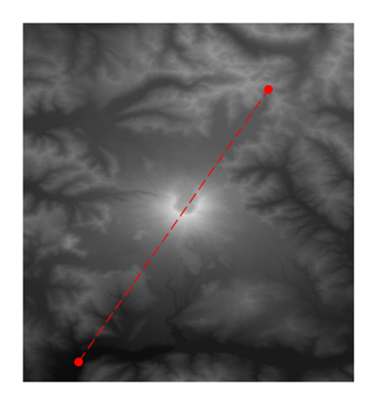
Figure 1 : Section line, shown as a red dashed line, on the DEM of Mount Saint Helens.
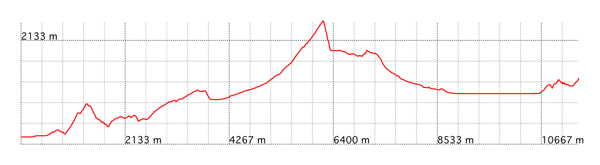
Figure 2 : Topographic profile obtained with the profile instruction.
Warning: each time the profile instruction is executed, either by pressing the `Return` key or by selecting the menu Cross Sections > Update View, there is a risk of overwriting the script containing the topographic profile and possibly other elements added by the user after work on the cross-section has started. For this reason, it is advisable to rename the script. In any case, before any potentially destructive action, GEOD displays a warning dialog box. To cancel the operation, simply click the Cancel button.
Obtaining the topographic profile along any curve with profile
The topographic profile may also be determined along any polyline or curve defined by a line or bezier command. In this case, one uses another syntactic form of the profile instruction:
profile "pathname" linename
where:
- pathname is the path of the script in which the topographic profile will be saved as a line command.
- linename is the name of the line or Bézier curve describing the section trace.
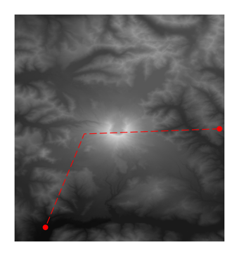
Figure 3 : Section line, shown as a red dashed line, on the DEM of Mount Saint Helens.
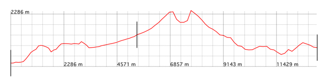
Figure 4 : Topographic profile obtained with the profile instruction along the section trace shown in figure 3. West is on the left and east is on the right. Break points are shown by the vertical black lines.
Scanning a DEM with xprofile
The xprofile instruction makes it possible to create a GEOD script storing a series of topographic profiles sampled across a DEM along north-south directions. In other words, this operation scans the DEM surface by varying the x coordinate of vertical section lines. The topographic profiles are stored as a single line instruction using the animation functions of GEOD.
The syntax is:
xprofile "filename"
where filename must be replaced by the name of the GEOD script to be created.
The script generated by xprofile produces an animation that gives an idea of the topographic surface.
This script may then be completed with other commands and instructions to provide a representation of the three-dimensional evolution of structures.
Scanning a DEM with yprofile
A similar instruction to xprofile is yprofile. This one scans the DEM surface along horizontal section lines, that is, in an east-west direction.
An example of application is shown in the original documentation.
Drawing contour lines on the DEM with contour
The contour instruction in GEOD makes it possible to draw contour lines on the DEM. The syntax is:
contour n ...
where n is the number of contour lines to be drawn, and the ... must be replaced by the sequence of the n altitude values of the contour lines.
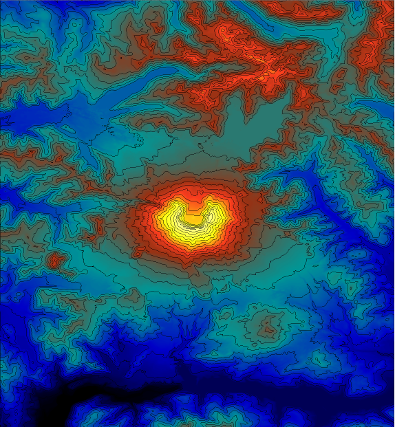
Figure 5 : Contour lines drawn on the DEM of Mount Saint Helens.