GEOD
fill (1)
Fill patterns: the fill command (1)
The fill command is used to fill a given area with a pattern. In this respect, GEOD provides functionality similar to that found in standard drawing software. This first part focuses on the markers used in fill patterns and on the grid used to position them.
Summary
- Usage
- Markers
- Marker types
- filled
- color
- markercolor
- width
- size
- dashed
- dotted
- char
- icon
- markerscale
- angle
- random
- The grid
- spacing
- hspacing
- vspacing
- alternate
- period
- filloffset
Usage
The fill command is used to fill an area with a periodic pattern. Its syntax is:
  fill
      ... -- subcommands of the fill command follow
Used on its own, this command produces nothing. It is normally followed by instructions defining the pattern itself or its background.
For example, the following instructions produce the result shown in Figure 1:
  fill
      fillcolor cyan
      square
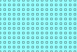
Figure 1: Fill pattern produced by the instructions fill fillcolor cyan square.
In fact, this pattern covers the whole active drawing area of the screen. In normal use, a fill command is combined with clip ... unclip to define its outline. For example, to draw a granitic pluton, one may write:
  clip pluton closed
      fill
          fillcolor salmon
          cross
  unclip
where pluton is the name of a Bézier curve delimiting the pluton.
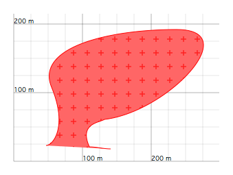
Figure 2: Fill pattern used to represent a granitic pluton.
A fill pattern is defined by:
- the use of one or several marker types,
- the horizontal and vertical spacing between the markers,
- their arrangement,
- their size, colour, line thickness, and related graphical properties,
- and the definition of a background, whether solid or graded, transparent or opaque.
The fill command can also be used to construct multi-layer patterns, opening the way to a broader range of possibilities.
Markers
Marker types
The markers available for the fill command are listed below. Similar instructions are also found in the pattern command.
- circle — circle
- verti — vertical line
- horiz — horizontal line
- square — square
- diamond — diamond
- cross — cross
- xcross — X-shaped cross
- triangle — upward-pointing triangle
- dtriangle — downward-pointing triangle
- asterisk — asterisk
- vee — V-shape
- basevee — V resting on a horizontal line
- dvee — inverted V
- ltilda — tilde-like symbol
- rtilda — reversed tilde-like symbol
- crescent — upward-facing crescent
- dcrescent — downward-facing crescent
- char — character
- icon — icon
By default, markers are drawn in black, as open symbols, with a line thickness of one pixel, and are inscribed in a rectangular box measuring 8 metres by 8 metres. They are arranged on a rectangular grid with a default horizontal and vertical spacing of 20 metres.
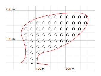
Figure 3: Fill pattern produced by the instruction fill circle.
filled
The filled instruction displays the filled version of a marker.
filled
For example, used together with circle, the instruction displays disks rather than hollow circles.
This instruction naturally applies only to markers with a closed outline, such as square, circle, diamond, triangle, and dtriangle.
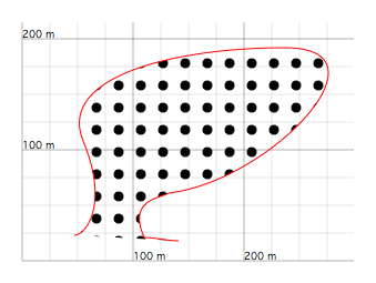
Figure 4: Fill pattern produced by the instructions fill circle filled.
Unlike the pattern command, a fill command, even with only one layer, may use several marker types at the same time. The symbols are then superimposed.
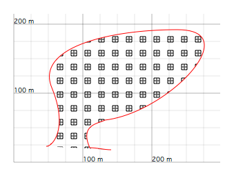
Figure 5: Fill pattern with a square symbol superimposed on a cross symbol, produced by fill square cross.
color
The color subcommand sets the outline colour of the marker.
The syntax is the same as for all colour-setting instructions in GEOD. A colour may be specified either by three numbers, red, green, and blue, each between 0 and 1:
color red green blue
or by giving the name of a recognised colour:
color colorName
See this section for the list of available colour names.
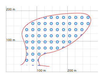
Figure 6: Fill pattern produced by the instructions fill circle color blue.
markercolor
The markercolor instruction specifies the fill colour of the marker. Calling this subcommand also has an effect similar to filled, since it automatically displays the filled version of the symbol.
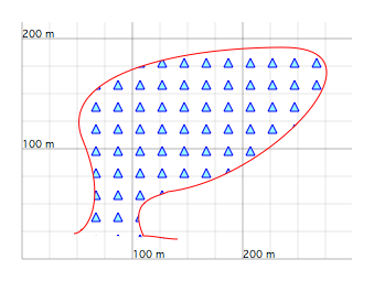
Figure 7: Fill pattern produced by fill triangle color blue markercolor cyan.
width
The width subcommand sets the thickness of the line used to draw the marker outline.
width e
where e is the line thickness in pixels.
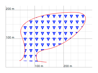
Figure 8: Fill pattern produced by fill dtriangle color blue markercolor cyan width 2.
size
The size subcommand sets the size of the marker.
size s
where s is the size, in metres, of the smallest square enclosing the marker. For example, for a circle, s corresponds to the diameter.
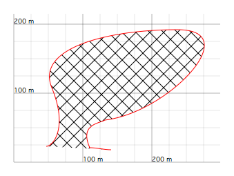
Figure 9: Fill pattern produced by fill xcross size 20.
dashed
The dashed instruction draws the outline of the markers as dashed lines. This subcommand can be used in its simple form, without arguments, or in a more elaborate form. Its syntax is described in detail here.
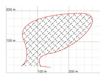
Figure 10: Fill pattern generated by fill xcross size 20 dashed.
dotted
The dotted subcommand displays the marker outline as a dotted line.
dotted
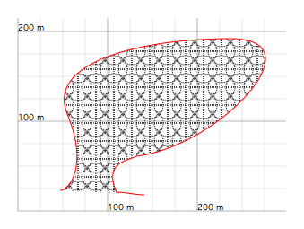
Figure 11: Fill pattern produced by fill circle cross size 30 dotted.
char
The char instruction makes it possible to use a character as the marker. It must be followed by the character to display. For example:
char @
produces the pattern shown below.
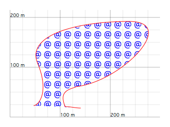
Figure 12: Fill pattern produced by fill char @ size 18 color blue.
icon
The icon instruction uses a small graphic file as the marker of the pattern. It follows the syntax:
icon "fileName"
where fileName is the name of the graphic file containing the image that will serve as the marker.
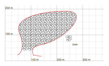
Figure 13: Fill pattern produced by fill icon "a.pdf".
markerscale
The markerscale instruction reduces, enlarges, flattens, or stretches a marker. It can be used in two different ways.
The first form is:
markerscale f
where f specifies the scale factor applied to the marker. This instruction performs a homothetic transformation of the symbol around its centre.
The second form uses two arguments:
markerscale fx fy
where fx and fy are scale factors applied respectively to the x and y coordinates of the points forming the marker outline. This makes it possible to stretch or compress a marker horizontally or vertically.
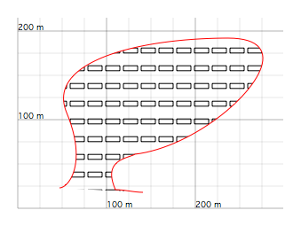
Figure 14: Fill pattern produced by fill square markerscale 2 0.7. The marker, initially a square, is stretched horizontally to produce a rectangle.
angle
The angle subcommand rotates the marker around its centre:
angle a
where a is the angle of rotation, expressed in degrees and measured counterclockwise.
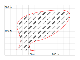
Figure 15: Fill pattern produced by fill square markerscale 2 0.3 angle 45.
random
The random subcommand makes it possible to generate patterns with random characteristics. It can affect the position, the size, and the orientation of the markers.
random position
randomly shifts the markers away from their initial positions.
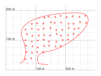
Figure 16: Fill pattern produced by fill cross color red random position.
random size
randomly changes the size of the markers.
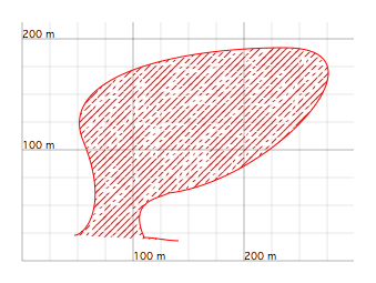
Figure 17: Fill pattern produced by fill verti random size color red angle -45 spacing 6. Each bar of the motif has a variable and random length.
random orientation
randomly rotates the marker around its centre.
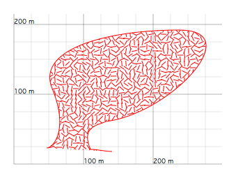
Figure 18: Fill pattern produced by fill verti color red spacing 6 random orientation.
The intensity of the random fluctuations generated by random can also be adjusted by specifying a second argument:
  random position f
  random size f
  random orientation f
where f is a number between 0 and 1. For f = 1, the instruction has its full effect, while for f = 0, the effects of random are cancelled. An intermediate value attenuates the fluctuations without removing them entirely.
The grid
The markers of a fill pattern are placed on the nodes of an invisible grid. By default, this grid consists of square cells 20 metres on a side. Its properties can be modified by several instructions.
spacing
The spacing subcommand sets the width of the grid cell, which is 20 metres by default.
spacing s
where s specifies the new cell width in metres.
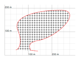
Figure 19: Fill pattern produced by fill cross spacing 10. The spacing has been reduced by half compared with the default marker spacing.
hspacing
The hspacing subcommand modifies the horizontal spacing of the markers.
hspacing e
where e is the new horizontal spacing of the grid.
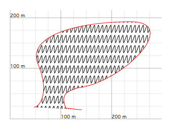
Figure 20: Fill pattern produced by fill ltilda hspacing 8 markerscale 1 4. The tilde symbols have been made contiguous to form a sinuous line. This is achieved by reducing the width of the grid to the size of the marker, 8 metres by default.
vspacing
The vspacing subcommand modifies the height of the grid cell.
vspacing e
where e is a numerical value specifying the new height.
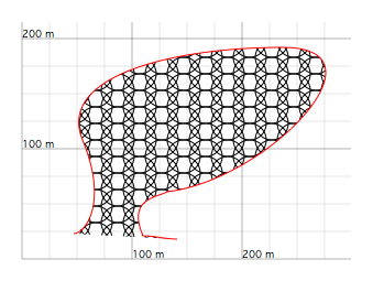
Figure 21: Fill pattern produced by fill circle vspacing 15 size 30. A tighter grid, smaller than the marker itself, can be used to create interesting visual effects.
alternate
The alternate instruction makes it possible to use a grid different from the default square grid. This subcommand takes no argument.
alternate
The new grid has a rhombic mesh, with a short diagonal oriented horizontally and 20 metres long, and a long diagonal oriented vertically and 40 metres high.
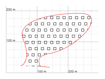
Figure 22: Fill pattern produced by fill square alternate.
period
The period instruction makes it possible to skip certain nodes of the grid when displaying the markers. This subcommand may be used with one or two arguments.
With one argument,
period n
the instruction tells fill to display only one marker out of every n markers that would normally be drawn.
With two arguments,
period n i
the instruction still keeps one marker out of n, but also specifies which one. The second argument i may take any value between 0, meaning that the first marker is kept, and n - 1, meaning that the nth marker is kept.
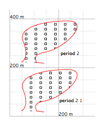
Figure 23: The period instruction. The fill patterns were produced by fill square period 2 in the upper drawing and fill square period 2 1 in the lower drawing.
filloffset
The filloffset instruction shifts the grid by a certain number of metres. This subcommand can be used in two different forms.
In the first case, it is followed by a single argument:
filloffset d
where d is the shift value in metres. The shift is then the same horizontally and vertically, so it takes place along a NE or SW direction.
In the second case, the subcommand is followed by two parameters:
filloffset dx dy
where dx and dy specify the horizontal and vertical shifts respectively.
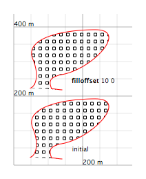
Figure 24: The filloffset instruction used to shift a pattern. The lower drawing shows the original pattern created by fill square. The upper drawing shows the same pattern shifted 10 metres to the right with filloffset 10 0.