GEOD
fill (2)
Fill patterns: the fill command (2)
This section presents additional features of the fill command, including background colouring, multi-layer motifs, the definition and use of predefined fill styles, and several other useful options.
Summary
- Background
- fillcolor
- alpha
- xalpha
- yalpha
- ralpha and calpha
- Multi-layer motifs
- Using predefined motifs
- Other options
- fore
- hidden
- x and y
- tie
- rotate
Background
The fill command also provides several instructions for adding a background to the motif, whether uniform or graded, opaque or semi-transparent.
fillcolor
The fillcolor subcommand creates a uniform background. Its syntax is similar to that of other colour-setting instructions.
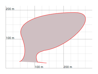
Figure 1: Applying a uniform background. The motif, here without markers, is created by the instruction fill fillcolor 0.81 0.75 0.76.
alpha
The alpha subcommand sets the transparency of the background of the motif:
alpha f
where f is a value between 0 and 1. When f = 0, the motif becomes completely transparent, that is, invisible. When f = 1, the motif is fully opaque, which is the default behaviour. Semi-transparency is obtained for values of f strictly between 0 and 1.
Note that this instruction affects not only the transparency of the background, but also that of all the markers.
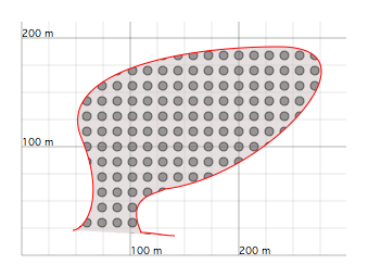
Figure 2: Semi-transparent fill pattern produced by alpha 0.5. Note that the grid remains slightly visible behind the markers. The fill pattern was generated by fill fillcolor 0.81 0.75 0.76 alpha 0.5 circle markercolor dkgray spacing 14 filloffset -1 -2.
xalpha
The xalpha instruction controls the transparency of both the background and the markers along the horizontal direction. This subcommand is followed by a parenthesized argument. The values inside these parentheses define the reference transparency values used to compute the gradient.
  xalpha (
      a1 at x1
      a2 at x2
      ...
      an at xn )
Here, a1, a2, ..., an are numbers between 0, full transparency, and 1, full opacity, while x1, x2, ..., xn are the horizontal coordinates at which these transparency values are assigned.
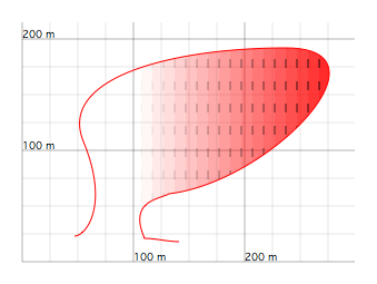
Figure 3: Fill motif with a horizontal gradient produced by an xalpha instruction. The motif was generated by fill verti fillcolor red hspacing 10 xalpha ( 0 at 100, 1 at 300 ).
The quality of the gradient depends on the horizontal spacing of the grid used by the motif. This spacing is 20 metres by default, but it can be modified by the instructions spacing or hspacing.
In Figure 3 above, the spacing is 10 metres, and the cells of the grid become visible in the gradient. The rendering can be improved by reducing the width of the grid cell.
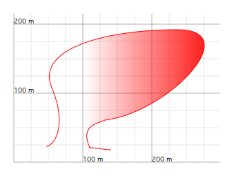
Figure 4: Fill motif with a horizontal gradient. The instruction hspacing 2 is used here, which greatly improves the smoothness of the gradient.
yalpha
Like xalpha, the yalpha instruction creates a gradient, but this time along the vertical direction. Its syntax is identical, and the same principles apply.
  yalpha (
      a1 at y1
      a2 at y2
      ...
      an at yn )
As with xalpha, the quality of the gradient improves when the vertical cell size is reduced. This can be done with the instruction spacing, which changes both dimensions of the grid, or more specifically with vspacing.
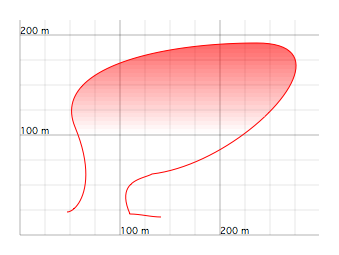
Figure 5: Motif produced by fill fillcolor red yalpha ( 0 at 100, 1 at 250 ) vspacing 4.
ralpha and calpha
The ralpha instruction creates a radial gradient. Like xalpha and yalpha, it is followed by a parenthesized list of transparency values defined at different radial distances r.
  ralpha (
      a1 at r1
      a2 at r2
      ...
      an at rn )
The radial distance r is measured from a point whose x and y coordinates are specified by calpha.
calpha x y
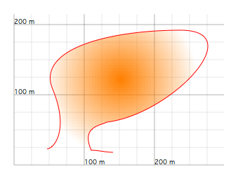
Figure 6: Motif with a radial gradient produced by fill fillcolor orange ralpha (1 at 0, 0 at 110) calpha 150 120 spacing 4.
As with xalpha and yalpha, the quality of the gradient depends on the dimensions of the grid. The instruction spacing can be used to reduce the cell size when needed.
Multi-layer motifs
Up to this point, only single-layer motifs have been considered, and these are sufficient in most situations. However, single-layer motifs do not allow:
- gradients between colours other than white,
- or the use of several marker types with different properties such as colour, fill, or size. Several marker types may be used in a single-layer motif, but they are always superimposed and always share the same attributes.
The solution is to use multi-layer motifs. A multi-layer motif is defined like a single-layer motif. To insert a new layer, one simply adds the keyword over. GEOD then draws the layers in the order in which they appear in the script. An example is given in Figure 7 with the instructions below.
  fill
      fillcolor red
      yalpha (1 at 50, 0 at 250)
      spacing 5
  over
      fillcolor yellow
      xalpha (0 at 50, 1 at 250)
      spacing 5
  over
      cross
      alternate
      spacing 40
      size 12
      color blue
  over
      circle
      spacing 40
      alternate
      filloffset 20
      markercolor red
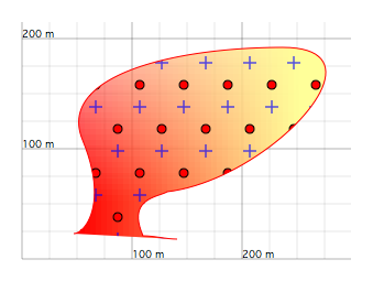
Figure 7: Example of a four-layer fill motif.
Using predefined motifs
If a motif is reused several times within the same cross-section, or across several scripts, it can be useful to define it once as a predefined motif.
A predefined motif is created with the set command in the following way:
  set fillName to fill
      ...    -- insert here the instructions of the fill command
where fillName is a user-defined name that will become the name of the predefined motif.
To apply this predefined motif in a fill command, use the keyword with:
fill with fillName
Predefined motifs may be defined anywhere in the script. They may even be defined in another script, which can then be inserted into the main script using an include command.
Predefined motifs offer a clear practical advantage. If one later decides to modify a motif, it is no longer necessary to search through the entire script for every fill command that uses it. Any change made to the predefined motif is automatically propagated to every fill command based on it.
This makes it possible to build a library of standard motifs commonly used in geology. For example, for a granite pattern, one could define once and for all the following predefined motif:
  set granite to fill
      cross alternate
      color red
To use this predefined granite motif, one would simply insert the following instruction into the script:
fill with granite
It remains possible to customize a motif based on a predefined style. For example, in Figure 8, the three motifs all use the same predefined granite pattern, but each one may still be modified, for instance by changing the background colour:
  fill with granite
      fillcolor ltgray
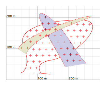
Figure 8: Predefined granite motif applied to several intrusive magmatic bodies.
Other options
fore
The fore instruction is a subcommand of fill. A similar option also exists for the pattern command, for the same reasons.
Indeed, GEOD draws motifs created by fill and pattern before all other objects, in order to preserve the visual quality of the lines and curves used as the boundaries of sedimentary layers or magmatic bodies.
In some cases, however, this behaviour creates a problem. This is illustrated in the figure below, where the contours of the older pluton are not hidden by the younger one.
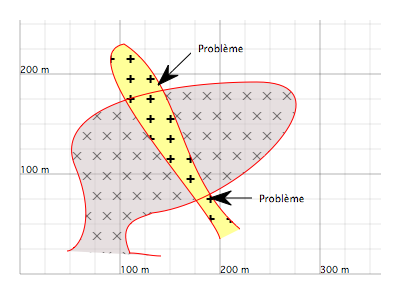
Figure 9: Cross-section with two intrusive bodies. In two places, the same drawing problem appears: the contours of the older pluton are not masked by the younger one.
To correct the figure, it is sufficient to use the fore instruction in the fill motif of the younger pluton. The contours of the older pluton are then properly covered by the younger one. In return, the border of the younger pluton becomes partly clipped.
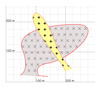
Figure 10: The same drawing as in the previous figure, but the errors have now been corrected using a fore instruction.
hidden
The hidden instruction hides the motif and cancels all other instructions. It is used without arguments:
hidden
x and y
The fill command also allows the user to define exactly where the markers should be displayed. For this, the x and y coordinates of the points must be provided explicitly:
  fill
      x ... y ...
      x ... y ...
      ...
where the dots must be replaced by the coordinate values.
The fastest way to define these points is to click with the mouse while holding down the Command key.
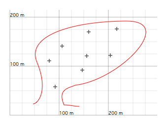
Figure 11: Fill motif with marker positions explicitly defined by the user.
tie
The tie instruction attaches a motif to an isolated point, defined by a point command, or to a point on a curve, defined by a line, bezier, offset, or shift command. This feature is especially useful for animations.
It allows a fill motif to follow the movement of an object.
To synchronize a motif with an isolated point, one writes:
  fill
      tie pointName
where pointName is the name of a point defined with a name instruction:
  point
      x ( ... ) y ( ... )
      name pointName
To synchronize a motif with a point on a curve, the fill command must be told how to locate that point on the curve. There are five different ways to do this:
1st possibility: the point is identified by its horizontal coordinate x:
  fill
      tie lineName at x ...
where lineName is the name of the curve, and the dots must be replaced by the coordinate value.
2nd possibility: the point is identified by its vertical coordinate y:
  fill
      tie lineName at y ...
3rd possibility: the point is identified by its curvilinear coordinate u:
  fill
      tie lineName at u ...
4th possibility: the point is identified by its depth:
  fill
      tie lineName at depth ...
5th possibility: the point is identified by its index:
  fill
      tie lineName at index ...
In practice, this makes it possible to keep a motif correctly attached to a moving structure during an animation.
rotate
The rotate subcommand is useful in animations. It rotates the motif. This instruction takes a single argument in one of two forms.
It may first be given as a single numeric value a, in degrees, measured counterclockwise:
rotate a
It may also be given as a time-dependent series of values enclosed in parentheses, specifying the successive angular positions a1, a2, ..., an at times t1, t2, ..., tn:
  rotate (
      a1 at t1,
      a2 at t2,
      ...
      an at tn )
This allows the fill motif to rotate together with the object to which it is attached.