GEOD
clip
The clip command
The clip command makes it possible to restrict, temporarily, all drawing operations, whether curves or patterns, to well-defined areas.
It is thanks to this command that geological cross-sections can be drawn compartment by compartment, without having to worry about lines or patterns extending beyond their intended limits.
In that sense, the clip command provides functionality somewhat similar to the “layers” of drawing software.
Summary
- The clip command
- Purpose
- General syntax
- Defining the boundary
- Boundary made of a single line
- Boundary made of several lines
- Boundary defined by points
- Boundary defined by points and curves
- Union of domains with or
- Union and intersection of domains
- Reusing a domain with with
- Debugging and adjustment options
- Previewing a domain with debug
- Adjusting a boundary with control
- Working compartment by compartment with only
The clip command
Purpose
The clip command is extremely useful whenever drawing must be restricted to a particular geographic sector, or when several graphic operations need to be associated with a well-defined domain.
An illustration is given below. During the first stage of constructing a geological cross-section, the layers may be drawn without worrying about the parts extending above the topographic profile. The clip command is then used to erase or mask these excess parts.
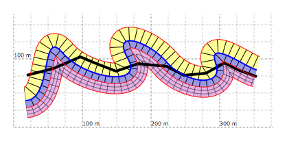
Figure 1a: Geological cross-section with its topographic profile, shown by the thick black line, and three folded layers. In this first draft, the layers extend above the topographic profile.
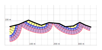
Figure 1b: The same cross-section, but with the parts above the topographic profile correctly removed using the clip command.
The usefulness of clip is not limited to this case. It becomes especially important when the cross-section includes faults, which is almost always the case. The clip command then allows the cross-section to be built compartment by compartment.
General syntax
To apply a clip command, two things are needed:
- the definition of the boundary that delimits the domain to be kept,
- and the list of objects, points, lines, Bézier curves, text, patterns, and others, that will actually be affected by the clipping operation.
For this reason, the clip command has several parts, which may in some cases be far apart in the script. The general syntax is:
  clip (boundary definition)
      ...
      ...
  unclip
with, in order:
- the keyword clip,
- the definition of the boundary delimiting the clipping domain,
- the usual GEOD instructions for drawing lines, Bézier curves, offset curves, translated curves, patterns, and so on,
- and finally the keyword unclip, which closes the instruction.
The main part of the syntax therefore concerns the definition of the boundary of the clipping area.
Defining the boundary
The boundary is defined using points, polygonal lines, or Bézier curves, together with directives specifying on which side the visible domain lies.
Boundary made of a single line
In the simplest cases, a single curve is used to define the boundary. This curve may be defined somewhere else in the script, or in another script included by an include command. The syntax is:
  clip lineName whichSide
      ...
  unclip
where:
- lineName is the name of the curve used as a boundary. This name must have been assigned earlier with the name instruction. The curve may be any curve type defined by line, bezier, offset, or shift.
- whichSide must be replaced by one of the keywords left, right, top, bottom, above, below, inside, outside, or closed. This keyword specifies which part of the figure remains visible after clipping.
In practice, clip in GEOD should be understood as clip and keep: keep the part indicated by whichSide.
Example:
  line
      100 150
      140 130
      110 120
      150 100
      name a
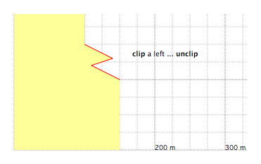
Figure 2: Filling a domain with clip ... left ... unclip. The red line is the boundary curve, named a in the script. The yellow fill, produced by a fill instruction placed between clip and unclip, is visible only on the left side of the figure.
Replacing left by another keyword changes the visible domain while keeping the same boundary.
With right, only the part on the right side of the boundary is kept.
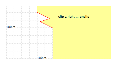
Figure 3: Filling a domain with clip ... right ... unclip.
With below, only the part immediately below the boundary is kept.
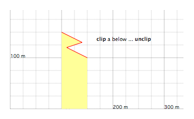
Figure 4: Filling a domain with clip ... below ... unclip.
With above, only the part immediately above the boundary is kept.
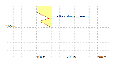
Figure 5: Filling a domain with clip ... above ... unclip.
With top, only the part immediately below the boundary is removed.
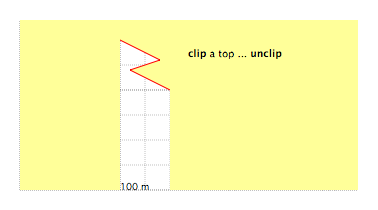
Figure 6: Filling a domain with clip ... top ... unclip.
With bottom, only the part immediately above the boundary is removed.
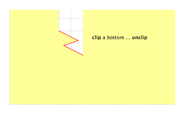
Figure 7: Filling a domain with clip ... bottom ... unclip.
With outside, only the part outside the boundary is kept. This becomes especially meaningful for nearly closed or fully closed boundaries.
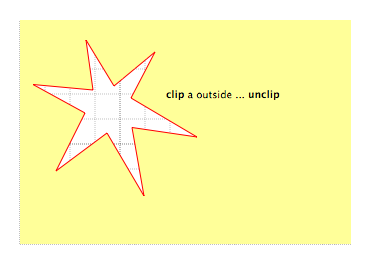
Figure 8: Filling a domain with clip ... outside ... unclip.
With inside, only the part inside the boundary is kept. The keyword closed can also be used in place of inside.
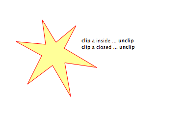
Figure 9: Filling a domain with clip ... inside ... unclip or clip ... closed ... unclip.
Boundary made of several lines
A domain may also be defined from several lines, using the syntax:
  clip line1 whichSide1
      line2 whichSide2
      ...
      lineN whichSideN
      ...
  unclip
where line1, line2, ..., lineN are names of curves, and whichSide1, whichSide2, ..., whichSideN are chosen among left, right, top, bottom, above, below, inside, closed, and outside.
As explained above, each instruction such as line1 whichSide1 defines a simple elementary domain bounded by a single curve. The final domain is obtained by the intersection of these elementary domains.
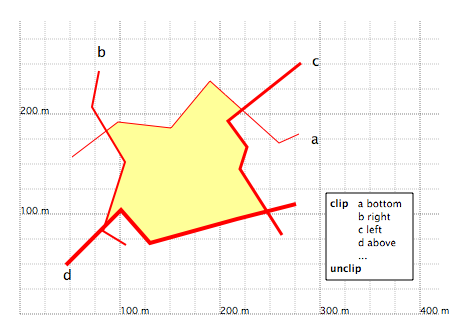
Figure 10: A domain formed by the intersection of four elementary domains. The letters are the names of the boundary lines. The corresponding clip ... unclip instruction is shown in the inset.
The same result could also be obtained by using several nested clip ... unclip instructions.
Boundary defined by points
A sequence of points, defined by their x and y coordinates, may be used instead of an existing curve to delimit the boundary.
  clip
      x ... y ...
      x ... y ...
      x ... y ...
      whichSide
      ...
  unclip
A more complex domain may also be built as the intersection of several elementary domains, each one defined by a sequence of points rather than by a line.
  clip
      x ... y ...
      x ... y ...
      x ... y ...
      whichSide1
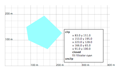
Figure 11: Domain whose boundary is defined only by points following the clip command.
Boundary defined by points and curves
Consider the example below. The thick black lines represent faults such as those that might be drawn on a structural sketch. One may wish to define the domain located between two such faults, named a and b.
A first attempt could be:
  clip a below
      b below
The result is not fully satisfactory, because the domain should be extended to the left and right beyond the ends of the faults.
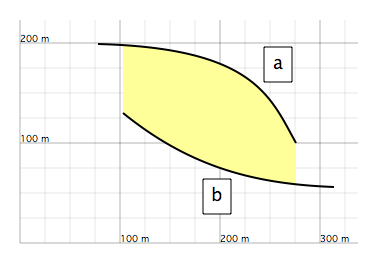
Figure 12a: Filling the domain between two faults, a and b. This first attempt is not fully satisfactory because the yellow area should be extended farther to the left and right.
One possibility would be to construct additional curves derived from a and b and extend them. A better solution, however, is to add extra points directly in the boundary definition. Points may be inserted before or after the name of the line.
  clip
      x ... y ...
      x ... y ...
      a
      x ... y ...
      x ... y ...

      below

      x ... y ...
      x ... y ...
      b
      x ... y ...
      x ... y ...

      above

      fill fillcolor yellow

  unclip
To position these extra points accurately, one may switch to Control mode. The points are then shown as red points that can be dragged with the mouse.
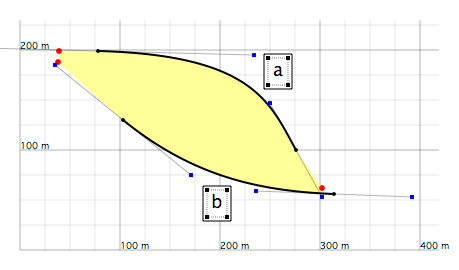
Figure 12b: Adjusting the end points in Control mode.
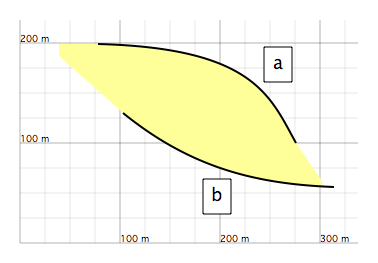
Figure 12c: Final result. The domain is now correctly filled, and the auxiliary points are hidden again.
Union of domains with the or instruction
All the clip examples seen so far define a domain through logical and conditions, for example, the region below line a and above line b.
It is also possible to define a domain by logical or conditions, for example, the region below line a or above line b. This is done with the keyword or.
The figure below shows three closed curves, drawn with Bézier curves, that may represent the map outlines of three granitic plutons cropping out at the surface. One may wish to fill the inside of these three plutons with the standard granite pattern made of crosses.
A repetitive way would be to write three separate clip ... inside ... fill ... unclip instructions, one for each pluton. A more efficient solution is:
  clip a inside
      or b inside
      or c inside

      fill xcross

  unclip
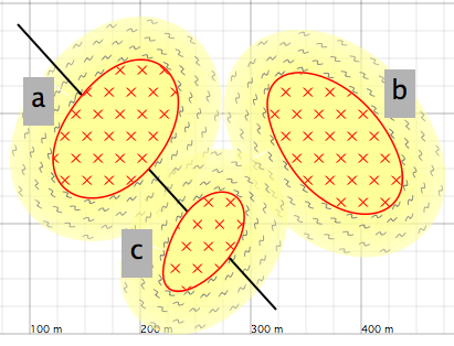
Figure 13: Representation of three granitic plutons on a map. The cross pattern, produced by a fill command, is delimited by a clip ... unclip instruction using the logical operator or. The metamorphic aureoles around the plutons are drawn with a pattern instruction.
Another example of the usefulness of or is shown below, with two reverse strike-slip faults, f0 and f1, defining a compressive pinched structure.
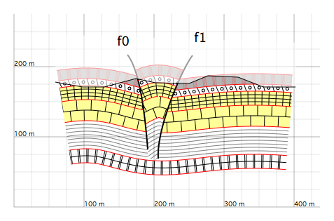
Figure 14: Cross-section of a pinched structure, a compressive structure associated with strike-slip motion.
To draw such a section, one may distinguish the internal compartment from the external part. Rather than defining three compartments, it is often better to define only two, an internal and an external one.
  clip f0 left or f1 right
      ...
  unclip

  clip f0 right
      f1 left
      ...
  unclip
In this way, all layers outside the pinched central compartment can be treated as a single continuous domain.
Union and intersection of domains
GEOD makes it possible to define a domain:
- either by intersection of broader domains, which is the default behavior of clip,
- or by union of subdomains, using the keyword or.
It is also possible to combine union and intersection in the same clip instruction.
The essential rule to remember is that, in GEOD, union has higher precedence than intersection.
For example:
  clip
      g1 inside or
      g2 inside
      topo below

  unclip
must be understood as: keep everything inside g1 or g2, and then remove everything above the topographic profile. It must not be interpreted as two separate conditions applied independently.

Figure 15: Cross-section with two intrusive plutons, drawn by two Bézier curves named g1 and g2. The fill of both plutons is delimited by a clip instruction combining both union and intersection.
Reusing a domain with the with instruction
A domain defined by a clip ... unclip instruction may be reused later in a GEOD script.
Consider the example below.
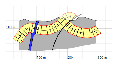
Figure 16: Draft geological cross-section, with sedimentary layers drawn first, followed later by intrusive bodies.
To construct this section, one follows the usual sequence:
- define the topographic profile with a line instruction,
- define the reverse fault,
- define the compartments on either side of the profile and the fault with clip ... unclip,
- in each compartment, define the master curves using bezier,
- offset the master curves with offset to construct the sedimentary layers, and apply a lithological pattern with pattern.
The section in Figure 16 also contains a dyke in the left compartment. Such objects are usually treated at the end, and the same can be done in GEOD. The dyke must remain confined below the topographic profile and to the left of the fault, here named f0.
A first solution would be to enclose all the dyke-drawing instructions in a new clip ... unclip block:
  clip topo below
      f0 left
      ...
  unclip
However, that same compartment has already been used earlier in the script for drawing the sedimentary layers. Rather than redefining it completely, it is better to reuse the domain already defined. This is done with name and with.
The earlier compartment is first given a name:
  clip topo below
      f0 left
      name f0left

  unclip
Then, to restrict the dyke drawing to this same compartment, one writes:
  clip with f0left
      ...
  unclip
Debugging and adjustment options
Defining domains may sometimes be difficult. The clip command provides several useful options for this purpose: debug, control, and only.
These instructions are mainly useful while the figure is being prepared, and are usually removed or commented out once the final version is obtained.
Previewing a domain with the debug instruction
Consider the example below, a cross-section with a fault network subdividing the section into many compartments. Each compartment must be handled by a clip ... unclip command.
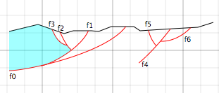
Figure 17: Draft geological cross-section with the fault network drawn.
As an exercise, the reader may try to write the corresponding clip instructions for the various compartments. Here, only the leftmost compartment, which is also the most difficult because it involves five curves, is considered.
  clip topo below
      f2 left
      f3 bottom
      f1 top
      f0 top

      debug
      ...

  unclip
In practice, it is often necessary to try out different keywords such as left, bottom, top, and so on. To check whether the clip command is correct, the debug instruction can be used. Inserted inside a clip ... unclip block, it fills the selected domain with a semi-transparent sky-blue colour.
In Figure 17, the domain is correctly delimited. But if, for example, above had been used instead of top after f1, the following incorrect result would be obtained:
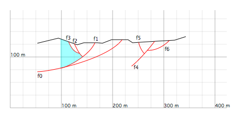
Figure 18: The same cross-section as in Figure 17, but with the left compartment incorrectly delimited, as revealed by the fill produced by the debug instruction.
Adjusting a boundary with the control instruction
As seen above, it is sometimes necessary to add extra points in order to delimit a domain properly. This is the case for the right-hand compartment in the cross-section below, where the lower side is not yet properly constrained.
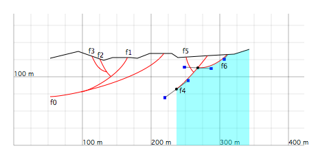
Figure 19: The same cross-section as in Figure 17. The right-hand compartment, highlighted by debug, is not bounded correctly along its lower side.
The solution is to complete the corresponding clip ... unclip instruction by inserting two extra points.
  clip topo below
      f6 bottom
      f4 right
      x ... y ...
      x ... y ...
      top
      debug
      control
  unclip
These two points can be added quickly by clicking in the figure while holding down the Command key. Adding the control instruction then makes them visible so that their positions can be adjusted by drag-and-drop.
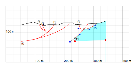
Figure 20: The same cross-section as in Figure 19. The compartment and its boundaries are now clearly visualized using debug and control.
Working compartment by compartment with the only instruction
A cross-section is generally drawn compartment by compartment. In some situations, when the drawing becomes very crowded, it may be useful to hide all the other compartments temporarily in order to focus on the one currently being worked on.
This is possible with the only instruction. It is inserted inside the clip ... unclip block, after the boundary definition.
  clip
      ...
      only
      ...
  unclip
If several clip ... unclip instructions in the script contain only, then it acts only on the last compartment defined in the script, and all the others are completely hidden.
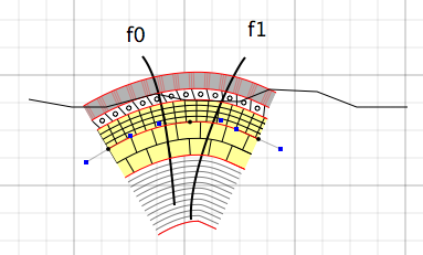
Figure 21: Returning to the cross-section of Figure 14. With the only instruction, the central compartment is isolated, making it easier to work on.