GEOD
text
Text
GEOD allows text elements to be inserted into a figure. Many subcommands are available to control both their visual appearance and their position.
Summary
- Insertion
- Position and dimensions
- Positioning text with xc and yc
- The control subcommand
- Setting the text box size with width and height
- The align subcommand
- The valign subcommand
- What to do when the text does not fit inside the text box
- Positioning text relative to another object
- The rotate subcommand
- Special characters
- Insert a line break
- Display the value of a variable
- Visual attributes
- Choose a font with font
- Set the font size with size or fontsize
- Use bold with bold
- Use italics with italic
- Change the text color with color
- Add a shadow with shadow
- Superscripts, subscripts, bold, and italic inside the text
- Framing text
- Different box types
- Set a background color with backcolor
- Set border color and thickness with bordercolor and border
- Use gradients with blend and blendcolor
- Raised boxes with emboss or recessed boxes with groove
- Predefined styles
- Define a text style
- Use a predefined style
Insertion
To insert a text element, simply use the text command with the following syntax:
text "..."
where the ... must be replaced with the text to be inserted.
GEOD places the text by default at the lower-left corner of the figure, at coordinates x = 0 and y = 0.
To position the text where you want in the drawing, there are two possibilities:
- enter the instructions x ... y ... in the script window, immediately after the line defining the text command.
- click on the drawing while holding down the Command key. In that case, GEOD inserts the instructions x ... y ... into the script and refreshes the figure.
  text "..."
      x 200 y 100
The inserted values specify the coordinates of the lower-left corner of the text box.
By default, the text is displayed in black, using the system font, with a font size of 10 points.
The text is left-aligned inside a text box, invisible by default, but which can be displayed with the control subcommand. The default text box is 100 metres wide and 15 metres high.
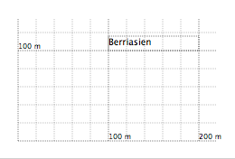
Figure 1: Inserting text into a figure. The text above was produced by the instruction text "Berriasian" x 100 y 100. A thin outline around the text shows the text box. This outline was displayed with the control subcommand.
Position and dimensions
Positioning text with xc and yc
The x and y instructions position the text by specifying the coordinates of the lower-left corner of the text box. It is also possible to position the text by specifying the coordinates of its center. This is done with xc and yc.
- xc sets the horizontal position of the center of the text.
- yc sets the vertical position of the center.
  xc 300
  yc 200
This places the text centered on the point with coordinates (300, 200).
An xc instruction can also be used together with y, and similarly yc can be used together with x.
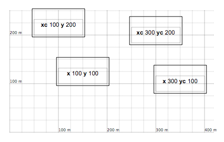
Figure 2: Positioning text with xc and yc. The thin outline, displayed with the control subcommand, shows the text box used by GEOD to position the text. The black border around the text was produced with the frame instruction.
The control subcommand
The control subcommand displays the position and size of the text box. It appears as a thin dashed outline around the text. This instruction is useful while preparing a figure.
control
Setting the text box size with width and height
The width and height subcommands change the size of the text box, which is by default 100 metres wide and 15 metres high. They are especially useful when the text is too long.
  width value
  height value
Here, value specifies the width and height of the text box in metres.
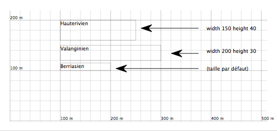
Figure 3: Using width and height to adjust the text box dimensions.
The align subcommand
The align subcommand controls the horizontal alignment of the text inside the text box. It recognizes three possible forms.
align left
aligns the text with the left edge of the text box. In practice, this instruction is rarely needed, since it is the default behavior of GEOD.
align center
centers the text inside its box.
align right
aligns the text with the right edge of the text box.
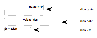
Figure 4: The align instruction. The text box is made visible with the control subcommand.
The valign subcommand
The valign subcommand controls the vertical alignment of the text inside its text box. GEOD does this by adjusting the size of the text box. This subcommand can be used in three forms.
valign top
places the text against the upper edge of the text box. This is the default behavior of GEOD.
valign center
vertically centers the text. To do so, GEOD reduces the height of the text box.
valign bottom
places the last line of the text against the lower edge of the text box. Again, GEOD recalculates the appropriate box height to achieve this.
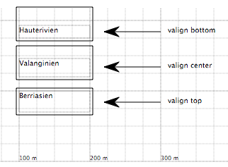
Figure 5: The valign subcommand. The thin outline, displayed with the control subcommand, shows the text box used internally by GEOD. The frame was produced with the frame instruction. valign controls the vertical adjustment of the text within this frame.
What to do when the text does not fit inside the text box
Sometimes the text is too long to fit inside the reserved text box. At least two solutions are available:
- enlarge the text box using width and height,
- use the instruction valign bottom, which automatically recalculates the box height so that the text can fit.
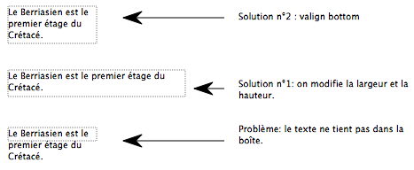
Figure 6: Different techniques for handling text that is too long. Note: because of a Mac OS X or PDF bug, the figure shown here may differ from what GEOD displays. In GEOD, text extending outside the text box is masked.
Positioning text relative to another object
It is possible to attach text to another object, such as a point, line, or curve, so that any movement of that object also moves the attached text. For this purpose, GEOD provides the subcommands above, below, left, and right.
These four instructions follow the same syntax.
- they can be followed by a name previously assigned to another object using the name subcommand,
- or they can be followed by the character \*.
  text "..."
      above theNameOfAnotherObject
  text "..."
      above *
In the second case, GEOD attaches the text to the last object, point or curve, defined before the text command.
Their meaning is explicit:
- above places the text above the object, more precisely above its highest part. The text is horizontally centered.
- below places the text below the object, more precisely below its lowest part. Again, the text is centered.
- left places the text to the left of the object, more precisely next to the part closest to the left edge of the figure. The text is right-aligned.
- right places the text to the right of the object, more precisely next to the part closest to the right edge of the figure. The text is left-aligned.
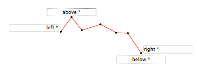
Figure 7: The above, below, left, and right instructions used to position text relative to another element of the drawing.
The rotate subcommand
The rotate instruction rotates the text around its anchor point specified by the x and y instructions. It is used as follows:
rotate angle
where angle is the rotation angle in degrees.
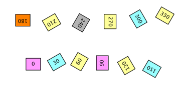
Figure 8: The rotate instruction used to rotate text. The numbers indicate the rotation angle in degrees.
Special characters
Special characters can be inserted directly inside the text written between double quotes in order to perform certain operations, such as forcing a line break or displaying the value of a variable.
Insert a line break
To force a line break in GEOD, use the character |.
text "The Berriasian|followed by a line break"
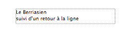
Figure 9: Inserting a line break with the | character.
Display the value of a variable
As will be seen later, GEOD allows variables to be defined. These may be simple constants or functions of time or space. This functionality becomes especially useful for layers and animations.
For example, one can define a time-dependent variable describing the variation of the x coordinate of a point through time. This is done with the instruction set ... to time ....
  set a to time
  ( 100 at 0, 200 at 1 )
In the instruction above, a variable named a is defined, varying linearly from 100 at t = 0 to 200 at t = 1.
To insert the value of this variable into a text, use the text command in the following form:
text "... %.2f ..." from a
Between the double quotes, the message to be displayed is inserted. The characters %.2f specify the format, here a floating-point number with two digits after the decimal point, in which the numerical value stored in the variable a will be displayed. The variable itself is indicated after the keyword from.
This instruction is especially useful in animations, when a text label must display the changing value of a variable through time.
Visual attributes
GEOD also allows the graphical attributes of the text to be modified, including font, color, style, and size.
Choose a font with font
By default, GEOD uses the usual system font to draw characters. To change the font, use the font instruction.
font "fontName"
where fontName is the name of a font. Double quotes are optional when the font name contains no spaces.
font "Impact"
font Impact
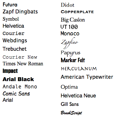
Figure 10: Changing the font with the font subcommand. The names above are fonts available on Mac OS X.
Set the font size with size or fontsize
By default, GEOD displays text with a font size of 10 points. To change this size, use fontsize.
fontsize 18
This sets the text to 18 points. When enlarging the text, it may also be necessary to enlarge the text box with width or height.
The instruction fontsize can be abbreviated as size.
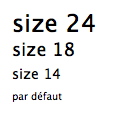
Figure 11: The size instruction used to change the font size.
Use bold with bold
To display text in bold, use the bold instruction.
bold
Note that this instruction does not work with all fonts. Arial, for example, supports it.
Use italics with italic
To display text in italics, use the italic subcommand.
italic
As with bold, this instruction only works with certain fonts, such as Arial.
With some fonts, bold and italic can be combined.
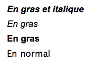
Figure 12: The bold and italic instructions used to change the style of the font, Arial in the example above.
Change the text color with color
To change the character color, use the color subcommand. It can be used in two different ways:
- followed by the name of a color recognized by GEOD. See the list of available color names.
- followed by three numerical values between 0 and 1 specifying the proportions of red, green, and blue.
color red
color 0.5 0.2 0.5
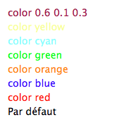
Figure 13: The color instruction used to change the color of the characters.
Add a shadow with shadow
It is possible to display text with a shadow in the background by using the shadow instruction.
It can be used either without argument:
shadow
In that case, GEOD creates a gray shadow behind the text, shifted by one pixel toward the lower-right corner of the figure.
Or with a numerical argument:
shadow 1.5
where the number controls the offset of the shadow relative to the text.
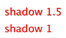
Figure 14: Adding a shadow to text with shadow.
Superscripts, subscripts, bold, and italics inside the text
Formatting instructions can also be inserted directly inside the text between the double quotes. This makes it possible to format selected characters as superscripts, subscripts, bold, or italic.
- for superscripts, enclose the characters with \S, uppercase S for *superscript*.
- for subscripts, enclose the characters with \s, lowercase s for *subscript*.
- for bold, enclose the characters with \b.
- for italics, enclose the characters with \i.
text "4/3 pi r \S3\S"
text "CO\s2\s"
text "text in \bbold\b"
text "text in \iitalic\i"
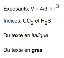
Figure 15: Inserting style commands directly inside the text.
Framing text
Different box types
GEOD can display text inside a frame. Five types of box are available. Use the corresponding instructions as follows:
- to display text inside a rectangular frame:
frame
- to display text inside a rectangle with rounded corners:
  frame
  round
- to display text inside an elliptical frame:
  frame
  oval
- to display text inside a diamond-shaped frame:
  frame
  diamond
- to display text inside a hexagonal frame:
  frame
  hexagon
The frame instruction draws a border around the text, a thin black line one pixel thick by default, and the subcommands round, oval, diamond, and hexagon allow another geometric shape to be selected instead of a rectangle.
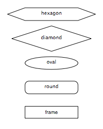
Figure 16: The different box types: frame, frame round, frame oval, frame diamond, and frame hexagon.
By default, GEOD keeps the text aligned to the left and to the top inside its text box. It is therefore often useful to center the text inside its frame with:
  align center
  valign center
Set a background color with backcolor
By default, GEOD displays text on a transparent background. A background color can be assigned to the framed area with the backcolor subcommand.
backcolor red green blue
where red, green, and blue are values between 0 and 1 specifying the color components.
A named color can also be used:
backcolor colorName
where colorName is a keyword recognized by GEOD. The color table is given here.
If you want to remove the border around the colored area, simply omit the keyword frame. For example, to display text in a cyan ellipse without border, write:
  backcolor cyan
  oval
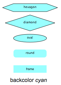
Figure 17: Setting a background color with backcolor.
To display reversed text, write:
  backcolor black
  color white
To make the background opaque without otherwise coloring it, use:
backcolor white
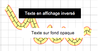
Figure 18: Writing reversed text or using an opaque background with backcolor.
Set border color and thickness with bordercolor and border
The frame subcommand draws a border around the text as a thin black line one pixel thick by default. This can be modified with border and bordercolor.
border controls the line thickness in pixels. For example:
border 5
draws a border 5 pixels thick. The thickness may be any positive real value. A thickness of 0 removes the border entirely.
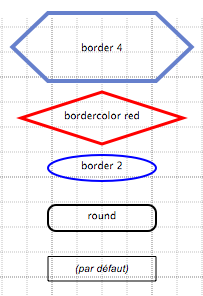
Figure 19: The appearance of these text boxes can be modified with border to adjust border thickness and bordercolor to change its color.
Use gradients with blend and blendcolor
Instead of a uniform background color, a gradient can be applied with the blend instruction. This subcommand takes no argument.
blend
By default, this creates a vertically oriented gradient between white, or more precisely the color defined by backcolor, and a medium gray tone.
To change the gradient color, use blendcolor.
blendcolor red green blue
where red, green, and blue specify the components of the tint. A named color can also be used:
blendcolor colorName
where colorName is a keyword recognized by GEOD. See the color table.
blendcolor sets the tint used in the upper part of the gradient.
For example, to create a gradient going upward from white to yellow, write:
  blend
  blendcolor yellow
To change the bottom color of the gradient, use backcolor. For example, to create a gradient from red at the bottom to black at the top, write:
  blend
  backcolor red
  blendcolor black
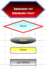
Figure 20: Using gradients in the background of a text box.
Raised boxes with emboss or recessed boxes with groove
Two 3D effects can be applied to text frames with the emboss and groove subcommands.
The emboss instruction creates a raised frame, with a light source coming from the upper-left corner of the figure.
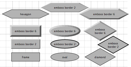
Figure 21: The emboss instruction used to display text inside a raised box.
The groove instruction creates a recessed frame, with a raised border and a sunken interior. Again, the light source is assumed to come from the upper-left corner of the figure.
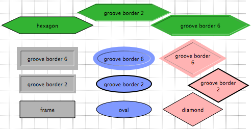
Figure 22: The groove instruction used to display text inside a grooved box.
The strength of the 3D effect can be adjusted by changing the border thickness with border.
Predefined styles
Several instructions are often needed to format a text. If several text objects share the same attributes, perhaps with small variations, it is better to define predefined text styles.
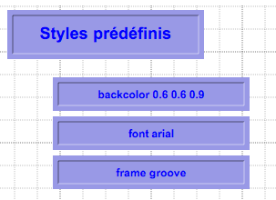
Figure 23: Using predefined styles to set the display attributes of text. The attributes of the four text boxes above were defined with a predefined text style.
Define a text style
To define a text style, use the set command as follows:
  set styleName to text
      ...
styleName is the user-defined name of the text style. The ... must be replaced by a series of instructions using subcommands such as font, size, fontsize, bold, italic, color, shadow, frame, backcolor, border, bordercolor, blend, blendcolor, emboss, or groove.
For example, the texts shown in Figure 23 use a predefined style named a, defined as follows:
  set a to text
      font arial
      size 18
      bold
      frame
      groove
      backcolor 0.6 0.6 0.9
      align center
      valign center
      color blue
Use a predefined style
To apply a predefined style to a text, simply use the instruction with followed by the user-defined style name.
  text "..."
      with styleName
In the example of Figure 23, the top text would be written as:
  text "Predefined styles"
      with a
Variants of a predefined style can also be used. For example, for the next three boxes in Figure 23, the same predefined style named a was used, but with a smaller font size, as in the following example:
  text "backcolor 0.6 0.6 0.9"
      size 12
      with a
The order of insertion of the instructions does not matter. In other words, it makes no difference whether size is placed before or after with.