GEOD
Grabens
Horsts and grabens
When the crust is subjected to extensional stresses, it breaks into separate blocks bounded by normal faults. The relative slip of these blocks is controlled by the geometry of the faults: some blocks, the grabens, subside relative to the others, the horsts. GEOD provides the tools needed to describe this type of crustal deformation.
Summary
Formation of a graben
The first step is to construct the blocks that will form the horsts. These are drawn in their initial configuration, before extension takes place.
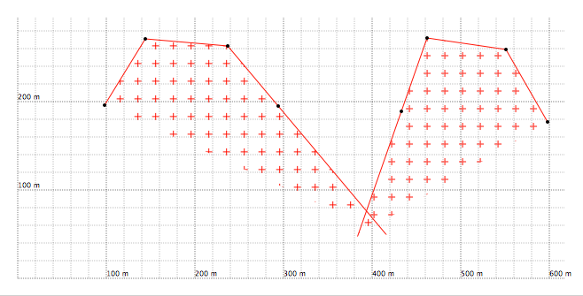
Figure 1: Two horsts constructed with the line command. The black points are control points entered in GEOD.
  For the block on the left
  line
      x ... y ...
      name b1
The next step is to define the lines or points that will serve as the framework for the subsiding graben block. Several approaches are possible. In the present example, two lines are drawn.
The following code gives the upper boundary of the subsiding block, shown as the blue line in the figure below.
  line
      tie b1 at u 180
      tie b2 at u 88
      name c0
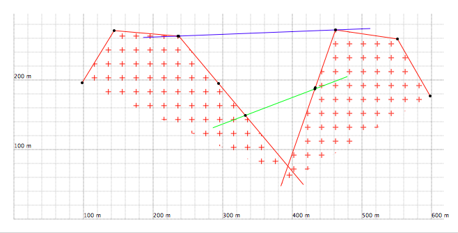
Figure 2: The blue line, representing the upper boundary of the subsiding block, together with the green intermediate line, forms the framework of the down-dropped block.
These two lines, the blue and the green ones, are attached to the horsts by tie ... at u instructions. They can therefore slide along the horsts, making it possible to simulate the subsidence of a graben.
Before doing so, the deformation parameters must be specified, in particular the horizontal separation of the two horsts as a function of time. For this, the translate command is used, which moves a line in a given direction.
  line
      ...
      translate (0 at 0, -50 at 1) 0
      name b1
The displacement vectors of blocks b1 and b2 are opposite in direction. Their amplitudes, 50 for b1 and 10 for b2, do not, however, need to be identical.
The parameters of the tie ... at u instructions must now be modified. The curvilinear coordinates of the points to which the blue and green lines are attached must necessarily vary through time. Otherwise, the subsiding block would stretch or contract locally, whereas its shape and volume should remain constant during the deformation.
The variation of these curvilinear coordinates must therefore be calculated. This is a purely geometric problem. The solution depends only on the dip of the two normal faults bounding the graben and on the total extension between the two horsts.
The variation of these curvilinear coordinates actually corresponds to the slip on the normal faults. To calculate these values, click on the Tools -> Graben menu in GEOD. A dialog box entitled Graben then appears. Open the Subsidence panel if it is not already displayed. Enter the dips of the two bounding faults, in degrees, as well as the maximum separation value. Then click on the Calculate button. The program displays the fault slip values. Note these values, here 65 for block b1 and 54 for block b2. These values can now be inserted into the GEOD script, giving respectively 245, that is 180 + 65, and 34, that is 88 - 54.
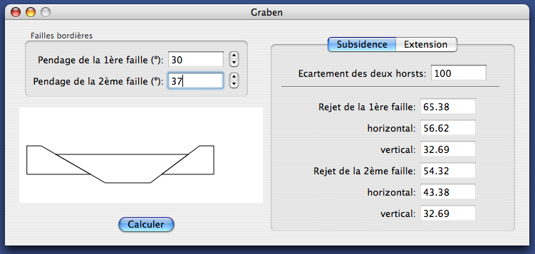
Figure 3: The Graben dialog box used to calculate slip along the bounding faults.
  line
      tie b1 at u (180 at 0, 245 at 1)
      tie b2 at u (88 at 0, 34 at 1)
      name c0
The initial and final states are shown below.
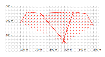
Figure 4: Initial state.
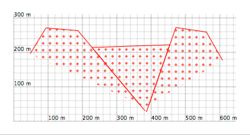
Figure 5: Final state.
Series of horsts and grabens
A more elaborate example can now be considered, involving a succession of horsts and grabens. The general procedure remains the same.
As in the previous example:
- the horsts are drawn first,
- their displacement vectors are assigned with the translate command,
- the blocks forming the floors of the grabens are constructed by attaching them to the bounding faults with tie ... at u ... instructions,
- the slip values along each bounding fault are calculated with the graben tool and inserted into the GEOD script,
- and the animation is then tested.
In the example treated here, an additional difficulty has been introduced. The horsts no longer move apart only horizontally, but may also undergo small relative vertical displacements. As a consequence, the subsiding blocks follow a more complex motion involving both translation and rotation. Note, however, that this added complexity does not change the calculation procedure described above.
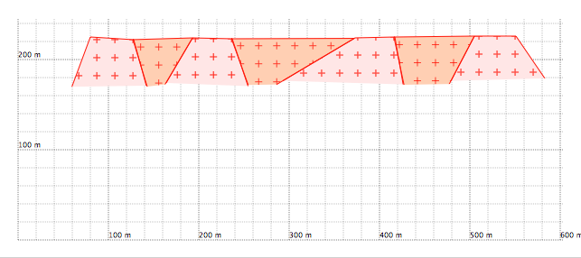
Figure 6: Initial stage before extension.
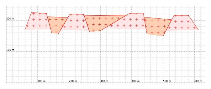
Figure 7: After extension. The rightmost subsiding block has tilted.
Reverse deformation
There is another way to describe block displacement in GEOD. This is to use move instructions, which displace a point along a given direction and over a given distance. For example, for a line delimiting a subsiding block resting on a horst named b1, one may write:
  line
      tie b1 at u 50
      move (0 at 0, 20 at 1) 50
      ...
In this example, GEOD is instructed to move one of the support points of the graben downward by 20 metres, corresponding to the fault slip, along a direction of 50°, corresponding to the dip of the fault.
The move command can also be used to simulate reverse deformation, that is, to reverse the sense of motion, passing from an extensional regime to a compressional one, so that formerly subsiding blocks are thrust back over the horsts.
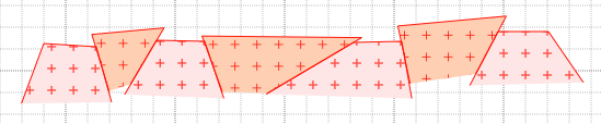
Figure 8: Reverse deformation of an ancient field of horsts and grabens.